Leaderboard

Popular Content
Showing content with the highest reputation on 02/15/2017 in all areas
-
Retrofit Heated Electric Wing Mirrors Special Tools: Uninsulated (W) Crimp tool Multimeter Pin removal tool (can be made fairly easily with a bit of fiddling around) Shopping list: 8X Various coloured 0.5mm sq cable approx 4-5 meters to be safe. (I used 1mm sq. cable and found it to be on the thick side for the switch) 2X Various coloured 1mm sq. cable approx 5-6 meters to be safe. (These lengths are just a guideline) 10X Female 2.8mm Terminals (Allowing for spares) 10X Male 2.8mm Terminals (Allowing for spares) 10X Male 1.5mm Terminals (Allowing for spares) 5X Heat shrink Butt Connector (Optional - solder can be used) 1/2X Loom tape (Not essential but finishes it off nicely. The linked tape is not OEM but you can find the OEM stuff on ebay - Tesa loom tape) 2X GTI or sport (OEM electric mirror) door harnesses 2X Manual mirror blanking plates 1X Electric mirror switch 2X Electric mirrors Your old door looms The latter of this list should be easy enough to get your hands on if somebody is breaking a sport or a GTI The mirror back cans can be swapped over easily. Door Looms And Mirrors: First off is the easy bit, swapping over the door looms and mirrors. This is pretty self explanatory - remove the old and fit the new, the manual adjuster plates should pull directly back. They are a pain. I must emphasise that the door looms are a must as they contain conduit that routes the wires safely up the door. Making a New Loom: For this you will need access to the back of the fuse box, the A pillar interconnects and behind the centre console for the switch, you (may) need to remove the passenger side trims up to the rear door cards and both sides of the dash so i advise stripping it all out at once. Firstly start with either the drivers or passenger side mirror wiring. Crimp the corresponding sized terminals onto the wires and push them into the BLUE connector block. To push them into the block you will need to release the PURPLE locking tab by pushing it in, you may need to give them a gentle tug with some pliers to get them to click in. You should now have a bundle of 3 wires inserted into the correct block, loosely route these to where they will go and cut to length, leaving some extra length in case of complications. Repeat this for the other side. Passenger side door: Drivers side door: Pin 1 - Black + Grey Pin 1 - Grey + Purple Pin 7 - Yellow + Black Pin 7 - Purple Pin 6 - Grey Pin 6 - Grey Heater Wiring: The heater wiring uses the thicker 1mm sq. cable. The way i routed this was a direct copy of the OEM layout. You can change the route if you like but i will not be held responsible for any altercations that may occur, USE YOUR OWN JUDGEMENT. I stuck to OEM spec because i figured they did it like that for a reason. You will need to run a new 5A fuse into the fuse box to number 18. This live feed gets tapped from the heated rear windscreen fused live, the OEM location for this is behind the rear passenger pocket under the door card as shown below. In the above picture you can see where the Black + Red and Black + Green wires for the heater circuit fit into the fuse box. Fuse Box: Pin 18A - Black + Green Pin 18B - Black + Red Rail A is for the 'feed' or 'live' wires, Rail B is the corresponding fused side. Once again, i recommend crimping the correct terminal onto the wire and inserting it into the terminal block first, then routing it as desired and cutting with length to spare. The fuse box PURPLE locking tab must be pulled out, this tab will pull out TWO clicks, you only want to pull it out ONE to allow pins to be inserted. The heater circuit runs through the BLACK connector block in the A pillar interconnect. Passenger side door heater circuit: Drivers side door heater circuit: Pin 1 - Brown Pin 1 - Brown Pin 5 - Black + Red Pin 5 - Black + Red The Black + Red wires are twinned behind the passenger side dashboard trim (this area contains multiple harness connections) so run your wires to this point and either crimp or solder them together, there should be three, drivers door, passenger door and fuse box pin 18B. Run the Black + Green wire up the passenger side and twin it with the heated rear screen wire (or alternatively twin it at the back of the heated rear windscreen switch pin 6 (The thicker black cable) Use a multimeter to confirm) The switch: The final part is wiring the switch. The connector that goes into the back of the switch just so happens to be the same fitment as the connecter in the any of the electric window switches (hence needing your old door looms). The connector housing is slightly different (straight down instead of to an L like the below picture) As you can see below, using the electric window connector, the wires hang down, so you will most likely need to trim a bit out of your switch panel underneath the mirror switch to get it to fit. As you can see above, in the middle slot, there is a blank pin. You can steal the blank pins out of the window connectors so you should be able to make a complete plug connector to either solder or crimp on to. Switch connector: Pin 1 - N/A Pin 2 - Grey - Twin both of the GREY wires you ran from either door Pin 3 - Brown - Earth (OEM earth is behind the passenger side dashboard trim) Pin 4 - Grey + Blue - Illumination (OEM connection is behind the passenger side dashboard trim) Pin 5 - Black - Live feed from fuse 26B Pin 6 - Grey + Black Pin 7 - Purple Pin 8 - N/A Pin 9 - Black +Yellow Pin 10 - Grey + Purple The neatest way to get a 12V feed from fuse box pin 26B is to remove that pin and cut the connector off at the base, bare the wire, twist your switch feed to that wire and crimp a new terminal on. Re-insert the terminal back into the fuse box and tape it up. You can either run a new earth or twin it with another, just make sure to check with a multimeter first. Grey + Blue wires behind the dash are most likely illumination wires so you can find and splice into another, more convenient illumination wire if you please, just make sure to check with a multimeter before cutting things up. Test your mirrors and heating elements to make sure everything works as expected. If everything goes to plan, box your car back up and enjoy your fancy new mirrors. I have made this guide as a few people have asked me now so i hope this helps. I have tried to be as comprehensive and clear as possible but if i have missed anything out or been unclear in sections just drop me a message and ill try to be of assistance.1 point
-
It was last MOT'd on November 7 2014 with 130,125miles on the clock. That MOT expired in 2015 and it was not tested after that. I checked the DVLA vehicle detail site but they could not find the car. I checked further and found that J7UPO is now attached to a 2003 SEAT Arosa (formally HX53HBK).1 point
-
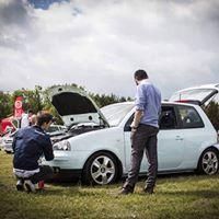
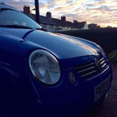
Its been a while since i last updated this! Not too much has happened really, had a rear hub replaced at the end of august for the new wheels to be able to go on properly, some more interior plastics were painted cream, i got a new headunit for my birthday and finally, my horn doesnt want to work when i push it and thats about it really! If anyone could give me any ideas as to what to do about my horn, that would be appreciated! (Already checked fuse and its fine) And now.. Pictures!1 point
-
I'm pretty sure all the arms are the same except the gti has longer bottom ball joint because of wider track, so they are talking ****. You can get the bushes on their own if you can get them in and out.1 point